|
ELECTROSOFT INGENIERIA |
Diseño de Electronica Personalizada - Diseño Digital & Analogico - Sistemas Embebidos - PCB Layout-Electronica Industrial & Fuentes Switching - Ingeniería Inversa / Reingeniería de Circuitos Impresos |
|
Tel: (56)-323610651 |
|
Localizador de Fallas de Cables Sísmicos o (Unidad de Prueba Cable MultiPar (UPCM))
Introducción
La Unidad de Prueba Cable Multipar o Localizador Fallas Cable Sísmico es un dispositivo que fue diseñado para detectar pares de cables dañados de largos cables multi-pares como los que se usan en Geofísica para interconectar sensores de aceleración y velocidad a los sistemas de adquisición de datos. Estudios de Geofísica se llevan a cabo normalmente en ambientes hostiles, por lo tanto, los cables multi-pares son propensos a sufrir daños debido a los animales, tira con fuerza y otras fuentes. Teniendo en cuenta que las longitudes de los cables están por lo general en el centenar de metros de distancia y también por el número de conductores, la localización de donde están fallados suele ser una gran molestia, sin la ayuda de un dispositivo como el Localizador Fallas Cable Sísmico Esta unidad permite al técnico a localizar de una manera rápida y eficiente los cables internos que están presentando problemas. La información de cable se muestra como 3 matrices en una aplicación compatible con Microsoft Windows proporcionado con la unidad
General Description The Multi-Paired Cable Tester (MPCT) is a device that was designed for detecting damaged cable pairs of long multi-paired cables as the ones used in Geophysics for interfacing acceleration and velocity sensors to data acquisition systems. Geophysics studies are normally carried out in harsh environments, therefore, the multi-paired cables are prone to damage due to animals, hard pulls and other sources. Considering that the cables lengths are usually in the hundred of meters range and also because of the number of conductors, fixing them can be a huge hassle without the aid of a device like the Multi-Paired Cable Tester. The MPCT allows the technician to locate in a fast and efficient way the internal cables that are presenting problems. The cable information is shown as 3 matrices in a Microsoft Windows® compatible application provided with the unit.
Matrices and Cable configuration The cable to be tested has two 27 pin female military round connectors (Connector A and C). Also the cable contains 12 pairs of banana connectors (Mueller terminals), where each pair consists of + and – terminal.
The software shows the status in 3 connection matrices, which are the following: (A) Red Connector Vs (C) Black Connector (A) Red Connector Vs Bananas (C) Red Connector Vs Bananas
The figure Fig 1 shows a physical scheme of the cable to be tested:
Fig 1. Physical scheme of the cable used for velocity and acceleration sensors.
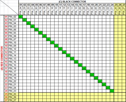
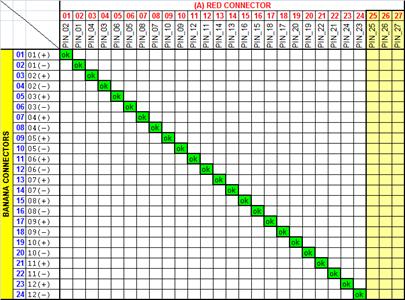
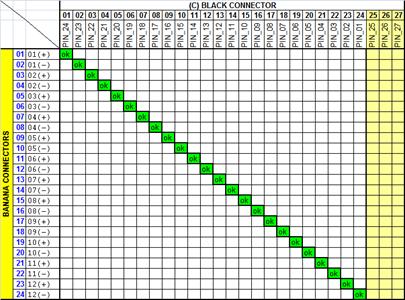
Connection Mapping The actual pin mapping between Connectors A and C and the bananas, is shown in the 3 following connection matrices. These matrices are the same ones that are shown in the software supplied with the MPCT. In this case the cable to be tested is error-free, so the information supplied by the matrices is actually the connection mapping. For the 3 matrices, correct connections are the ones that lay exactly on the diagonal. Because the cable in this case is ok, every diagonal is filled with the OK green mark.
If the cable to be tested was defective, the 3 matrices would show the incorrect connections, so the technician can go directly to the conflicting connection and repair it.
Fig 2. (A) Red Connector Vs (C) Black Connector
Fig 3. (A) Red Connector Vs Bananas
Fig 4. (C) Black Connector Vs Bananas
Application Diagram The following diagram shows the way of connecting the cable to be tested (DUT). The device under test or DUT has two 27 pin female military round connectors.
Fig 5. Connection Diagram Both ends of the cable are connected to their respective connectors on the MPCT metal box. As shown in figure 5, there is a third connector called banana connector clip, which is an alligator style clip intended for connecting to the banana connectors that are along the cable. The software when checking the cables, will ask the user to connect the clip to a specific banana terminal on the cable depending on the mode of operation. The modes of operation are listed in the features section.
Features Track down errors in multi-paired cables in a fast, efficiently and easy way. The failing pairs location are shown in the 3 connection matrices. Detects missing and extra connections. A Short circuits is declared if the pair resistance is less than 200ohms. An open circuit is declared if the pair resistance is more than 400ohms. It is possible to save the status of the tested cables, so the data can be restored in any moment. 3 Modes of operation: Mode1: Complete check of A-C and 12 bananas connections (One Shot). Mode2: Complete check of A-C connections (Loop Mode). Mode3: Specific check of a banana connection defined by the user. Hardware compatible with USB 2.0 standard. Software compatible with Microsoft Windows Xp ™, Vista™ and 7™ versions.
|
|
Copyright 2019 Electrosoft Ingeniería |